
When last we spoke, the examination of the two lower receivers from C3 Defense (www.c3defenseinc.com) had concluded and we had initiated the construction of the upper receiver for the economy rifle, with all the remaining parts from Del-Ton, Inc. (www.del-ton.com).
Having the completed upper in hand, we move on to installing the barrel. Make sure the upper receiver threads and the threads of the nut are completely clean and free of foreign objects, like burrs, dirt, grease, or blood.
BARREL
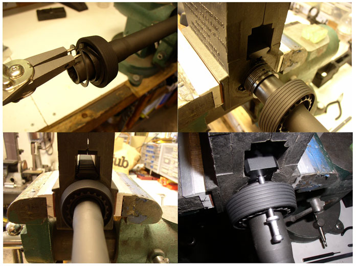
The most difficult chore here is to install the snap ring on the delta ring. While not absolutely required, snap ring pliers are very, very useful here. The barrel should have the serrated barrel nut already installed. Place the large angled aluminum delta ring around the rear of the barrel nut, with the small diameter facing forward.
The large weld spring can then be placed against the rear of the angled ring. The split snap ring is then placed on the nut and pushed home into the groove on the barrel nut. This compresses the weld spring, so that there is forward spring tension on the delta ring.
Then, simply insert the barrel into the upper receiver, making sure that the locator pin on the barrel extension makes its way into the notch on the top of the receiver. It should be a loose fit. If not, heat the receiver threads with a propane hand torch for about ten seconds and then it should slide right on.
Apply anti-seize in a liberal amount (liberal as in copious, not as in political) to the receiver threads and hand tighten the delta ring and nut to the receiver.

Taketh up thy AR action wrench and matcheth thy wrench’s scallops to those of thy barrel nut. You will have to push the delta ring back in order to insert the wrench’s teeth fully into the nut’s teeth. Tighten. Use a torque wrench (if you have one) with your action wrench and tighten to about 30 foot pounds.
If you haven’t a torque wrench, give it a small “oomph.” Loosen and tighten again; then go further the necessary amount to align the next hole in the nut serration to the hole going through the upper receiver. It may be a little, it may be a lot. Generally, once it’s oomph tight, you can still go almost a full hole segment further if you have to. I should point out that 30 foot pounds is a lot lighter than you think. It’s effectively a minimum spec anyway.
GAS TUBE
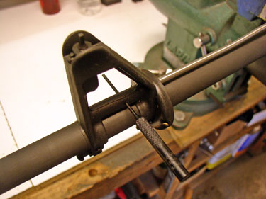
This is the trickiest part of the assembly of the upper. The end with the little knobby is the back end that goes into the receiver, and the end with the holes goes into the front sight gas block. With the upper in your vise, insert the back end through the barrel nut and into the upper receiver.

You will have to rotate the tube so that the bend in it allows the front end to clear the front sight, though you may still have to flex it just a bit to do so (a small amount is okay). It should slide right in, and if it doesn’t, then take it back out and ensure that you can see all the way through the delta ring, weld spring, nut, and snap ring. All should be aligned so that the tube will pass through into the upper receiver.
HANDGUARD
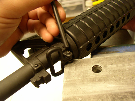
Now all you do is install the two-piece handguard. Include your wife in the project by having her insert the handguard halves while you are pulling the delta ring back. It is a stout spring. Install the top half first (they are identical) making sure you have the front ears properly inserted into the front retaining ring, just behind the front sight tower, and around the gas tube.
Snap in the rear end, and then do the same for the bottom half. Push the delta ring forward to fully seat it on the handguard. You will probably feel a little play in the handguard, but very little, and this is correct. If you want to feel more manly, rejecting your wife’s assistance, get a handguard removal tool from Brownells.
CHARGING HANDLE, BOLT, AND CARRIER
The charging handle, if not assembled already, involves simply putting the spring in the hole in the left side of the “T”, inserting the latch and stuffing the little roll pin in to retain it. Starting the pin before inserting the spring and latch, and retaining the latch with a punch will make things easy. Just drive the pin in and the punch will fall out.
The firing pin should move freely within the bolt bore and in the pin hole in the cam. Ensure that it does so prior to assembling the bolt/carrier assembly. Push the bolt into the carrier with the extractor on the right side.
The cam pin should then be inserted through the carrier and into the bolt and rotated ninety degrees so that the short sides of the pin’s top are pointed to the sides of the carrier. The firing pin then goes down the middle of the assembly from the rear and is retained by the little cotter style pin, which is inserted into the large chamfered hole on the left side of the carrier. Test the fit of the bolt by pulling it all the way forward and standing the assembly upright on the bolt face. It should not collapse.

If it does, and a new one should not, the gas rings should be replaced. It should also not require more than light force to move it. Too much friction, and difficulty moving, will prevent proper cycling and may be indicative of poorly manufactured parts. I know that’s subjective, but there is a feel to it, and in this regard, with new parts, you are very unlikely to encounter a problem.
The firing pin should move freely without restraint. Hold the assembly with the bolt pointing straight up, and flick the back of the firing pin.
If it doesn’t bounce up and down freely, then you probably have a problem with the bolt’s cam pin hole/cam pin interface, meaning you will likely need a different bolt as the hole is not properly sized or crimped. The firing pin should also only protrude through the bolt face when the bolt is entirely pushed into the carrier.
CONCLUSION
That’s the upper assembly. We’ll finish next month with the construction of the lower receiver. This was the basic assembly of the run-of-the-mill rifle. Of course, the deer rifle was significantly different. Since that goes onto a more upperclassmen type of assembly, I won’t go into great detail.
That upper was a JP Enterprises CTR-02 upper that I received and promptly took apart to have another feature from another company added. We’ll discuss that in our next excursion.
Gun Digest Guide to Customizing Your AR-15
Whether you’re in the brainstorming phase of planning the future of your AR-15 and what it will become, or you’re already applying the finishing touches to your custom AR-15 creation, Gun Digest Guide to Customizing Your AR-15 by Kevin Muramatsu will help you wade through and understand the wide variety of available options for almost every imaginable variation. Though the array of AR accessories and customization options seems to constantly grow, turn to this book for an examination of the customization landscape and helpful recommendations for which options would work best for the growing population of AR owners.


![Best Concealed Carry Guns In 2025 [Field Tested] Wilson Combat EDC X9S 1](https://gundigest.com/wp-content/uploads/Wilson-Combat-EDC-X9S-1-324x160.jpg)


![Best 9mm Carbine: Affordable PCCs [Tested] Ruger Carbine Shooting](https://gundigest.com/wp-content/uploads/Ruger-Carbine-Shooting-100x70.jpg)
![Best AR-15: Top Options Available Today [Field Tested] Harrington and Richardson PSA XM177E2 feature](https://gundigest.com/wp-content/uploads/Harrington-and-Richardson-PSA-XM177E2-feature-100x70.jpg)
